- Home
- Tube Laser Cutting Machine
- Vertical Three Chucks Tube Laser Cutting Machine FLT-7035ETP
Vertical Three Chucks Tube Laser Cutting Machine FLT-7035ETP
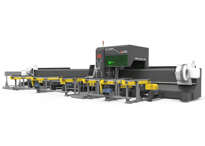
The FLT-7035ETP tube laser cutting machine is the latest addition to our range of vertical three chucks machines. This machine has been designed specifically for the cutting of tubes and profiles with a diameter of up to 350 mm. The FLT-7035ETP is a highly versatile machine that can be used for a variety of applications, including the cutting of round, square and rectangular tubes, as well as profiles with different shapes and sizes.
The FLT-7035ETP tube laser cutting machine is equipped with a state-of-the-art CNC control system that ensures precise and accurate cuts. The machine also features a powerful laser system that allows for high speed and efficiency when cutting tubes and profiles.
Technical Parameters
| Maximum cutting length | 7000mm |
| Maximum weight for each tube | 500kg |
| Cutting diameter | 15-350mm O.D. |
| Rotary speed | 60rpm |
| X.Y.Z axis position accuracy | ±0.05mm/m |
| Minimum tailing | ≥0mm |
| Maximum running speed | 60m/min |
| Power supply | 380V/50Hz |
Components
Feature
The main use and application scope of the product
It is mainly used for round, square, rectangular, elliptical and waist round tubes of common carbon steel and stainless steel, etc. The outer circle size of cutting workpiece is Φ15-Φ350mm, the maximum length of raw material is 7000mm, and the down length is 0~7000mm.
The main composition of the product
The main components of FLT-7035ETP series laser pipe cutting machine are: main machine tool, chain type automatic loading frame, chain type automatic unloading frame, control system, low voltage electrical system, laser, water chiller, extractor fan, etc.
Machine tool host part
The host part of the machine is the main component of the whole laser pipe cutting machine, the cutting function and cutting accuracy of the laser pipe cutting machine are realized by the host part, the host part consists of the bed, up and down with the support, chuck, X / Z axis device, auxiliary system (protective outer cover, air and water), operation screen and other parts.
Chain type automatic loading and unloading device
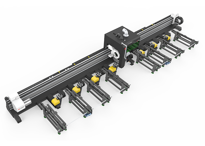
3 sets of chain type loading and unloading devices are designed on the loading side and the unloading side respectively.
2.3 Electrical control part
Laser pipe cutting machine electrical control system is an important part to ensure the running trajectory of various graphics, the general electrical control system is mainly composed of CNC system and low-voltage electrical system.
The machine tool CNC system is configured with Bertru high-performance bus type 5000A CNC system, which is based on windows operating platform, stable and reliable operation, contains 32-bit microprocessor, can be used with nesting software.
Low voltage electrical system
The low-voltage electrical system is located in the electric control cabinet, which is the interface part of the electrical control of the whole machine. All the original components of the electrical system are made by famous manufacturers at home and abroad to ensure that the whole machine is stable, reliable and responsive in operation. The drive motor is AC servo motor, AC servo motor for driving the X-axis, Y-axis, AW (synchronous rotation) axis of the machine tool, characterized by good acceleration performance, fast response speed, X,Y-axis maximum positioning speed up to 60m/min; machine tool Z-axis for the feed axis, using AC servo motor (with holding brake) for driving: that is, Z-axis cutting head, characterized by good dynamic response characteristics, both with the control and can be NC control.
The fiber laser
The fiber laser used has higher photoelectric conversion efficiency, lower power consumption and better beam quality compared to traditional lasers. The laser is compact, maintenance-free operation and ready for use. Due to its flexible laser output method, it can be easily integrated with system equipment.
Auxiliary peripherals
Including water chiller, exhaust system, etc.
Beds and Chucks
The bed and the chuck adopt the side hanging connection design to facilitate the loading and unloading operation of large diameter pipe.
The bed is welded with 8~10mm wall thickness square pipe and 40~20mm steel plates, which are divided into 3 sections and connected by high strength bolts and positioning keys to ensure the geometric accuracy after connection. After welding, it is treated by annealing to eliminate internal stress, and then finish machining after rough machining and vibration aging, thus greatly improving the rigidity and stability of the machine tool and ensuring the accuracy of the machine tool.
The chucks are divided into 3 groups of pneumatic chucks: front, middle and rear. 3 groups of chucks driven by servo motor can move and rotate synchronously in Y-axis direction. Under the logic action set by the system, it can realize the pulling type cutting of the pipe, which can greatly improve the cutting accuracy and can conditionally realize the zero tail material cutting (depending on the workpiece cutting size and specific cutting process).
The Y-axis movement drive rack, roller linear guide and W-rotation drive gear of the chuck are all made of high precision products, which effectively ensure the accuracy of transmission; each group of chucks is controlled by limit switches and equipped with hard limit devices, which effectively ensure the safety of machine movement.
X, Z axis device
This is only a schematic diagram of the structure, the actual design is subject to the final design
The X-axis beam and side columns are of gantry type structure, welded with high quality carbon steel plate, annealed to eliminate internal stresses, and then finished by vibration aging after rough machining to ensure the rigidity and stability of the moving parts of the laser head. The beam is fixed on the bed, equipped with high quality linear guide rail, driven by servo motor, through the high quality rack and pinion drive, so that the Z-axis sliding plate to achieve reciprocating motion in the X direction. In the process of movement, the limit switch controls the stroke to limit, and at the same time there are elastic cushion mechanical limits at both ends to ensure the safety of the system operation.
Z-axis device is mainly to realize the up and down movement of the laser head. The up and down movement of the laser head is controlled by a servo motor controlled by the CNC system.
The motor drives the ball screw, which drives the Z-axis slide plate up and down to complete the reciprocating motion. The upper and lower ends are controlled by proximity switches to ensure the safety and reliability of the movement. The linear modules are made of high quality products to ensure the accuracy of transmission.
The Z-axis can be used as a CNC axis for its individual interpolation motion, while it can be linked with X and Y axes, and can be switched to the follower control to meet the needs of different situations. Since the Z-axis follower is also controlled by the CNC system, the accuracy of the follower is high and the stability is good, thus ensuring the quality of cutting.
After the capacitive sensor in the Z-axis device detects the distance from the nozzle to the surface of the plate, the signal is fed back to the control system, and then the control system controls the Z-axis motor to drive the cutting head up and down, thus controlling the constant distance between the nozzle and the plate and effectively ensuring the cutting quality. The cutting head can automatically adjust the focal distance, and adjust the position of the focal point according to the material and thickness of the cutting material, thus obtaining a good cutting section.
Upper and lower material follower support device and centering device
The upper and lower material sides are designed with 3 groups and 4 groups of follower support devices respectively. The first group of support on the lower material side adopts pallet type structure, which is convenient for short workpieces to be loaded. Each group of support device has horizontal movement and lifting function, driven by servo motor. The loading side can transport the pipe from the loading rack to the bottom of the chuck, and then lift the pipe to the right height for chuck clamping. The lower feeding side can transport the finished cut workpiece to the lower feeding device and then the finished part will be transported out by the lower feeding device.
Each set of supports has a separate servo motor driving the up and down movement of the pallet assembly. During processing, for rectangular tubes, the upper feeding side follows the support device and the system adjusts the height of the pallets assembly in real time according to the outer contour of the tube to ensure that the pallets support the tube stably. When the chuck moves to the corresponding position, the auxiliary support automatically drops for avoidance.
The auto-centering device automatically centers the delivered pipe in place so that the chuck can accurately hold the pipe.
Chain type loading and unloading device
Both the loading and unloading sides use a chain conveyor structure to transport, load and unload the tubes.
The conveyor chain is designed with several groups of swinging stations, which can place multiple pipes. By motor drive, the pipe can be transported horizontally to the upper feeding position for the main machine to lift.
Together with the multiple sets of follow-on palletizing devices on the upper and lower sides of the main machine, it can realize the handling and lifting of the upper material of the pipe as well as the receiving of the lower material and the transportation of the finished parts.
Electrical Control System
The FLT-7035ETP three-chuck pipe cutting machine electrical control system is mainly composed of Bertrud CNC 5000A bus type system, servo system and low voltage electrical system.
frequently asked question
Do you have CE? We provide you with CE in the form of a one-stop service. At first, we will demonstrate CE to you. After delivery, we will give you CE packaging list a commercial invoice for customs clearance.
Please tell us about your following answer, our specialist will provide advice on proper power. 1. What material you want to cut, stainless steel, carbon steel or other? 2. What thickness do you want to cut?
If confronted with any problems, please contact us immediately and do not attempt to fix the machine by yourself or anyone else. We will respond within 24 hours as quickly as we can to help you.
2 years quality guaranty, the machine with main parts(excluding the consumables) shall be changed free of charge(some parts will be maintained) when if any problem during the warranty period.
Yes, we are happy to provide advice and we have dedicated technicians all around the world who are ready to assist you. Your operations’ continued success relies on your machines staying in working order.
Leave Message And Get The Answer
In order to improve the user experience and improve our production technology, JQ laser has been collecting real machinery handling questions and comments from the market, which we will analyze and provide answers to, and we will also adopt the favorable production ideas.


